A digital circuit is presented for the Towers of Hanoi problem based upon its iterative algorithm. This provides a case-study to illustrate synchronous design principles and the correspondence between hardware and software functions.
In a recent correspondence[1], Chedid and Mogi presented an iterative algorithm for the Towers of Hanoi problem to illustrate a simple method for replacing recursion with iteration. In this correspondence we show how the iterative algorithm can be further transformed into a digital circuit design.
In brief, the Towers of Hanoi problem is a game with three pegs and a pile of n disks of differing widths stacked on one peg such that no disk is on top of a smaller one (and thus the disks form a pyramid). The objective of the game is to move the stack to another peg, one disk at a time without placing any disk on top of a smaller one. The iterative algorithm is reproduced below for reference.
        { Move stack from peg 1 to peg 3 }
        Procedure ITERATIVE_HANOI:
        Let FromPeg, ToPeg be array [1 ... n] of 1 ... 3;

        Set FromPeg to {1, 1, 1, 1, ... 1}
        If n is odd then
           Set ToPeg to {3, 2, 3, 2, ... 3}
        Else
           Set ToPeg to {2, 3, 2, 3, ... 3}

        For i := 1 to 2^(n-1) do
           begin
           Find the largest d (1 <= d <= n) such that i mod 2^(d-1) = 0
           Move disk d from peg FromPeg[d] to peg ToPeg[d];

           case[FromPeg[d], ToPeg[d]] of
              [1,2] FromPeg[d] := 2 ToPeg[d] := 3;
              [2,1] FromPeg[d] := 1 ToPeg[d] := 3;
              [1,3] FromPeg[d] := 3 ToPeg[d] := 2;
              [3,1] FromPeg[d] := 1 ToPeg[d] := 2;
              [2,3] FromPeg[d] := 3 ToPeg[d] := 1;
              [3,2] FromPeg[d] := 2 ToPeg[d] := 1;
           end; {case}
        end; {for}
        end; {procedure}
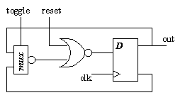
The design uses purely synchronous techniques in which all state-elements are (positive) edge-triggered flipflops. No asynchronous operations are permitted: thus, for instance, a toggle flipflop with reset would be implemented as in figure 1.
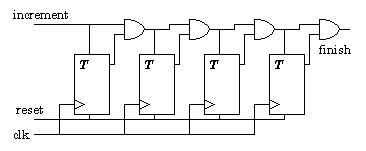
Consider the variable i in the iterative algorithm which is the main control operator. This is a simple incrementing counter which is implemented using only toggle flipflops and AND gates. Each bit (flipflop) of a binary counter changes (toggles) only if all the less significant bits (flipflops) are HIGH: the chain of AND gates in figure 2 provides this signal to each flipflop.
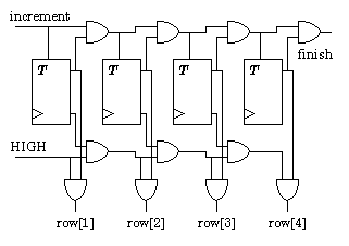
The variable d can be seen as the index of the first non-zero bit of the counter. Since d is used to address a row in each of the two arrays, the row-address lines are generated directly (rather than encoding it as an address to input to an address decoder). Building upon the similarity between the definition of d as the first non-zero counter bit and the generation of the counter toggle signal, the row-address signal generation is combined with the counter as shown in figure 3. Thus a single row-address is HIGH if the corresponding counter bit is HIGH AND all less significant bits are LOW.
The two two-bit arrays, FromPeg and ToPeg, are implemented using Enable flipflops: the stored value is updated (on a positive clock edge) only if the enable control signal is HIGH. To allow for the initialization of the two arrays as described in the algorithm, there are two different Enable flipflop: one which initializes to zero, E(r), and the other which initializes to one, E(s). Two different collections of four Enable flipflops are defined to implement the two possible initialization values in the algorithm (i.e. ToPeg[i] = 2 or 3).
The row-address signal is used to update the array values in the selected row which is done according to the case statement in the algorithm. A quick inspection shows that the FromPeg bits take on the value of the ToPeg bits - and logic minimization (e.g. with Karnaugh maps and don't-care states) shows that the ToPeg values can be generated using two NAND gates as shown in figure 4.

The row-address signal is also used to enable a tristate bus connection for the outputs of the enable flipflops; the values on this bus indicate the numbers of the source and destination pegs for the current disk move. The disk number is actually redundant since it is always the top disk which is moved - however, a simple disk number circuit can be designed (based on multiple-input NOR functions) to transform the row-address signals into a binary number.
Towers of Hanoi circuits for a specific number n of disks can be built using a bit-slice approach for the counter and memory arrays. The algorithm is terminated by the finish signal shown in figure 2. A Towers of Hanoi circuit with a programmable n can be built provided that n has a maximum value. In this case, the array is designed for the maximum number. One problem is the initialization of the arrays which varies between odd and even values of n. This can be solved by either renumbering the pegs (the engineering approach) or by designing a circuit which swaps the output values 2 and 3 as appropriate to the value of n. For a programmable version, the disk number circuit and a comparator are necessary to terminate the algorithm when the disk to be moved has a number greater than n.
We have shown the design of a digital architecture based upon a software algorithm which can be used to illustrate: 1) a correspondence between hardware and software elements, and 2) synchronous design principles. The simplicity of the solution may recommend itself to the students.
The author is a Senior Lecturer at
the Department of Electrical Engineering, The University
of Edinburgh, The King's Buildings, Edinburgh, EH9 3JL,
Scotland, UK.